
Description
DEIF
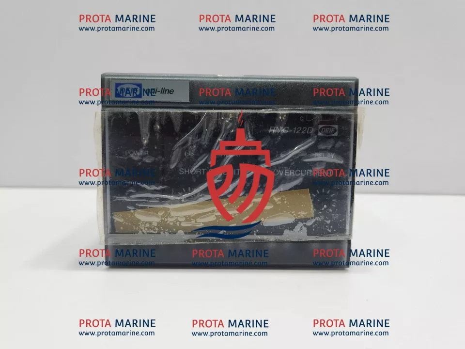
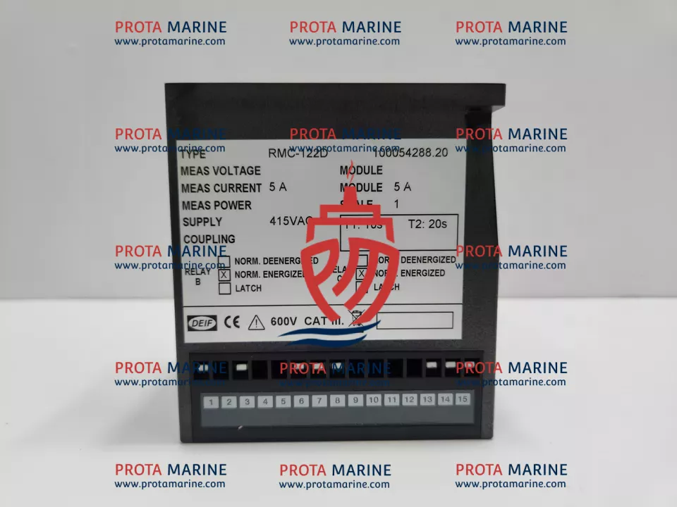
TYPE: RMC-122D UNI-LINE
100054288.20
SHORT CIRCUIT RELA
FEATURES:
SHORT CIRCUIT AND OVER-CURRENT
I>>: 100 TO 400 %, I>: 50 TO 150 %
COMBINED FUNCTIONALITY
SHORT CIRCUIT RELAY (I>>)
ANSI CODE 50 AND 51
MEASUREMENT OF 3-PHASE CURRENTS
LED INDICATION OF FAULT CONDITION
TIMER-CONTROLLED TRIPPING
LED INDICATION FOR ACTIVATED RELAY
35 MM DIN RAIL OR BASE MOUNTING
TECHNICAL SPECIFICATIONS:
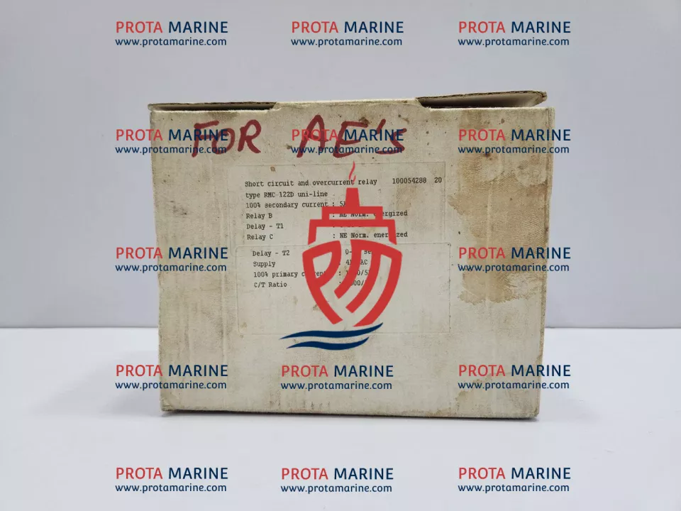
100% SECONDARY CURRENT: 5A
RELAY B: NE NORM. ENERGIZED
DELAY-T1: 0-10 S
RELAY C: NE NORM. ENERGIZED
DELAY-T2: 0-20 SEK.
SUPPLY: 415VAC
100% PRIMARY CURRENT: 1500/5A
C/T RATIO: 1500/5A
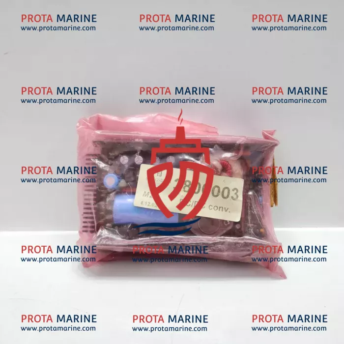
The DEIF RMC-122D Uni-Line Short Circuit Relay (part number 100054288.20) is a combined short circuit and over-current protection relay designed for integration within marine control systems. Conforming to ANSI codes 50 and 51, it provides dual-function protection across three-phase current measurement circuits, making it a critical component in shipboard power distribution and protection panels. Its role in detecting fault conditions and executing timer-controlled tripping ensures that electrical systems onboard remain protected from damaging overcurrent events, safeguarding equipment continuity and reducing the risk of cascading electrical failures at sea.
Key Features
✓ Combined short circuit (I>>: 100–400%) and over-current (I>: 50–150%) protection in a single relay unit, conforming to ANSI codes 50 and 51 for standardised marine electrical protection.
✓ Operates on a 415VAC supply with a CT ratio of 1500/5A and a 5A secondary current rating; timer-controlled tripping with Relay B delay T1 of 0–10s and Relay C delay T2 of 0–20s, subject to confirmation against specific panel configuration.
✓ Compatible with DEIF Uni-Line protection relay systems; suitable for integration into marine switchboards, generator protection panels, and distribution control systems where standardised DIN rail components are specified.
✓ Designed for 35mm DIN rail or base mounting, suitable for installation within enclosed switchboard or MCC enclosures; LED indication for fault conditions and activated relay status supports rapid fault diagnosis onboard.
✓ Replacement of this relay should be carried out by qualified marine electricians with reference to the original panel drawings and DEIF documentation; compatibility with existing CT ratios and supply voltage must be verified prior to installation.
Marine Applications
✓ Shipboard main switchboards and bus-tie panels requiring overcurrent and short circuit protection across three-phase distribution circuits.
✓ Generator protection systems on commercial vessels, offshore platforms, and naval auxiliaries where ANSI 50/51 relay functions are specified.
✓ Motor control centres (MCCs) and feeder protection panels aboard tankers, bulk carriers, container ships, and passenger vessels.
✓ Offshore support vessels and FPSOs where reliable three-phase fault detection is essential to maintaining power system integrity during critical operations.
✓ Retrofit and upgrade projects on vessels requiring replacement of legacy protection relays within DEIF Uni-Line or compatible switchboard architectures.
Why Marine Engineers Choose
The DEIF RMC-122D combines two essential protection functions — short circuit and over-current — into a single compact relay with clear LED diagnostics, adjustable time delays, and a robust DIN rail mounting format. This reduces panel complexity, supports faster fault identification, and aligns with recognised ANSI protection standards trusted across commercial and offshore marine electrical systems.
Ideal For
Commercial cargo vessels, tankers, bulk carriers, container ships, passenger ferries, offshore support vessels, FPSOs, and any marine or industrial application requiring ANSI 50/51 compliant three-phase overcurrent protection within a DEIF Uni-Line control architecture.
Technical Support & Compliance
Technical support is available for remote troubleshooting, onboard assistance, commissioning, and integration of this relay into existing marine control systems. Retrofit and upgrade guidance can be provided subject to review of the vessel’s existing protection scheme. To confirm compatibility and ensure correct supply, buyers are advised to share nameplate photographs, the full part number, relevant panel drawings or single-line diagrams, the existing CT ratio and supply voltage details, switchboard model and manufacturer information, and vessel name or IMO number where applicable. All compatibility assessments are subject to confirmation based on documentation provided.